
What Is a Wiring Diagram?
Wiring Diagram is a visual plan that shows how electrical devices, conductors, terminals, and protective components connect within a circuit. Standard symbols identify each part, while lines show electrical paths and connection points. Electricians use the diagram to trace circuits, verify intended connections, diagnose faults, and guide repairs or installation work.
Quick Facts About Wiring Diagram
Category
Electrical documentation
Used for
Circuit tracing and troubleshooting
Common confusion
A wiring diagram is not a floor plan
Also called
Electrical Wiring Diagram
Often discussed with
Electrical Troubleshooting
Key Takeaways About Wiring Diagram
- Symbols represent devices and connection points.
- Lines show intended electrical paths.
- A wiring diagram is not a physical layout.
How Wiring Diagram Works
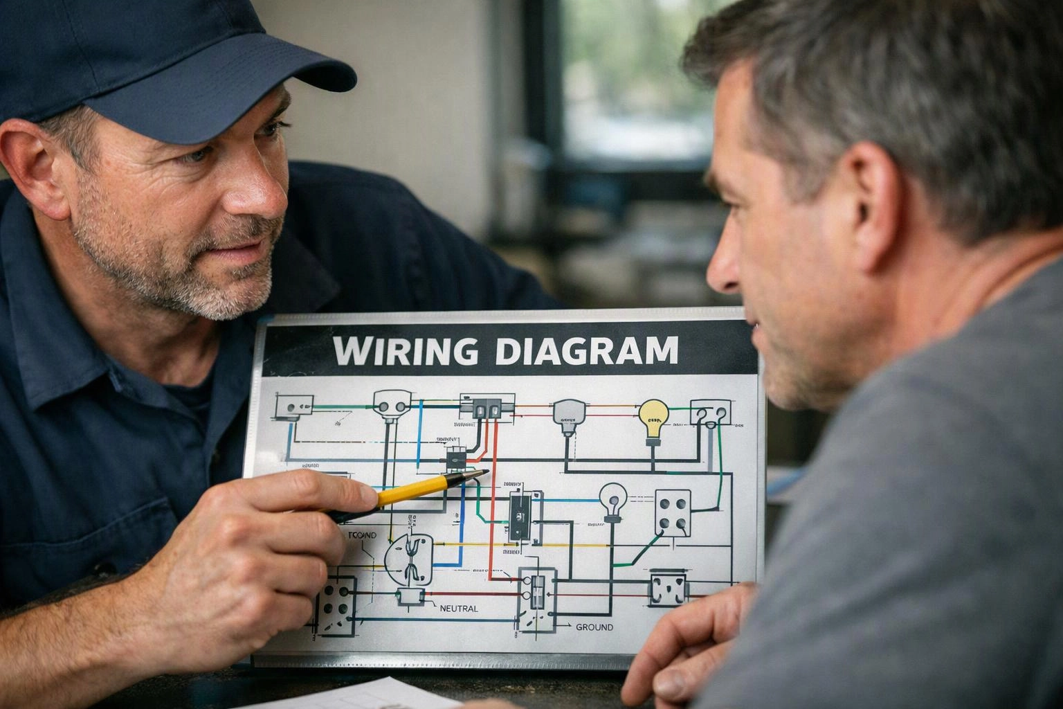
Wiring diagram symbols represent circuit parts, including switches, receptacles, loads, conductors, and protective devices. Lines connect those symbols in the order that current is intended to travel. Labels identify wire functions, terminal points, and connections that may not be obvious from a finished installation.
Related glossary terms: Continuity Test, Multimeter, Panelboard.
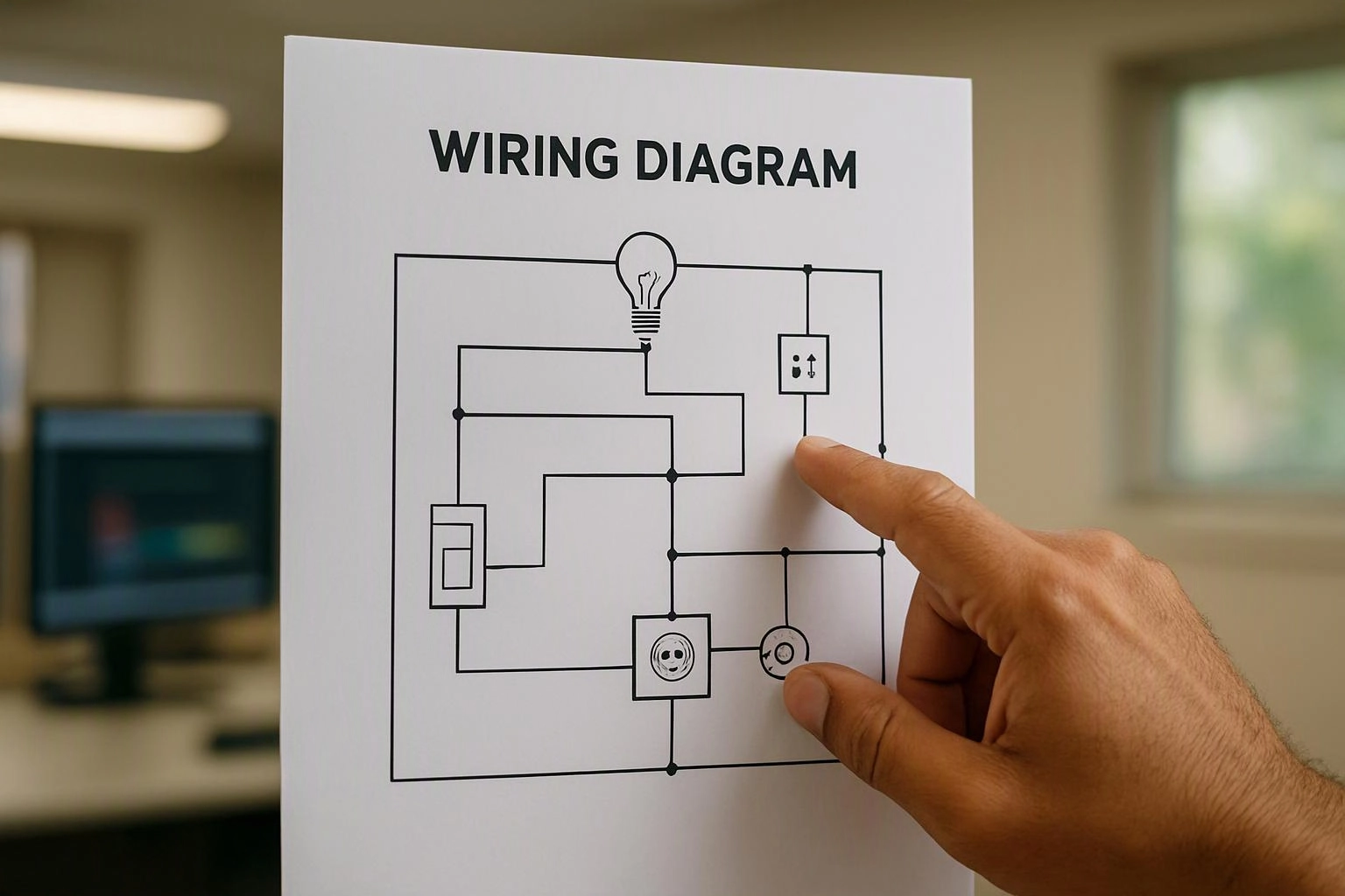
An electrician follows the diagram during testing by comparing the shown path with the actual wiring. A break, unexpected connection, loose termination, or incorrect conductor can explain why part of a circuit does not operate correctly. A multimeter can help check voltage or continuity at points shown on the diagram. A panelboard diagram can also show which circuit supplies a branch circuit, helping narrow the search during electrical troubleshooting.
From the GMB Electric team
When we troubleshoot a circuit, we compare the available wiring diagram with the installation before testing individual conductors. Our team checks device locations, conductor paths, terminal connections, and panel references. If the diagram does not match the wiring, we document the actual arrangement before deciding where the fault lies.
Wiring Diagram in Practice: A Real-World Example
A homeowner reports that several outlets stopped working after a switch replacement. A wiring diagram helps the electrician trace the shared circuit, identify the intended feed and switched conductors, and check whether a connection was placed on the wrong terminal.
Related Services
Related Terms
Continuity Test
A continuity test is an electrical check that determines whether a circuit path is complete from…
Multimeter
A multimeter is a handheld electrical testing instrument that measures values such as voltage, current, and…
Panelboard
A panelboard is an electrical enclosure that holds circuit breakers, busbars, and connection points for distributing…
Circuit Breaker
A Circuit Breaker is a resettable electrical switching device that opens a circuit when current exceeds…
GMB Electric
Have Questions About Wiring Diagram?
Contact GMB Electric for practical guidance on Wiring Diagram and related 24 hour electrician work in Indianapolis.