
What Is a Continuity Test?
A continuity test is an electrical check that determines whether a circuit path is complete from one point to another. A meter sends a small test signal through the path and indicates whether current can pass. The result helps identify open wires, loose connections, damaged conductors, or broken components during electrical troubleshooting.
Quick Facts About Continuity Test
Category
Electrical diagnostic test
Used for
Finding open circuits and broken connections
Common confusion
Continuity does not confirm full circuit performance
Typical tool
Multimeter
Also called
Continuity check, Circuit continuity test
Often discussed with
Electrical Troubleshooting
Key Takeaways About Continuity Test
- It checks for a complete electrical path.
- A meter helps locate open or damaged wiring.
- Continuity does not prove a circuit operates under load.
How Continuity Test Works
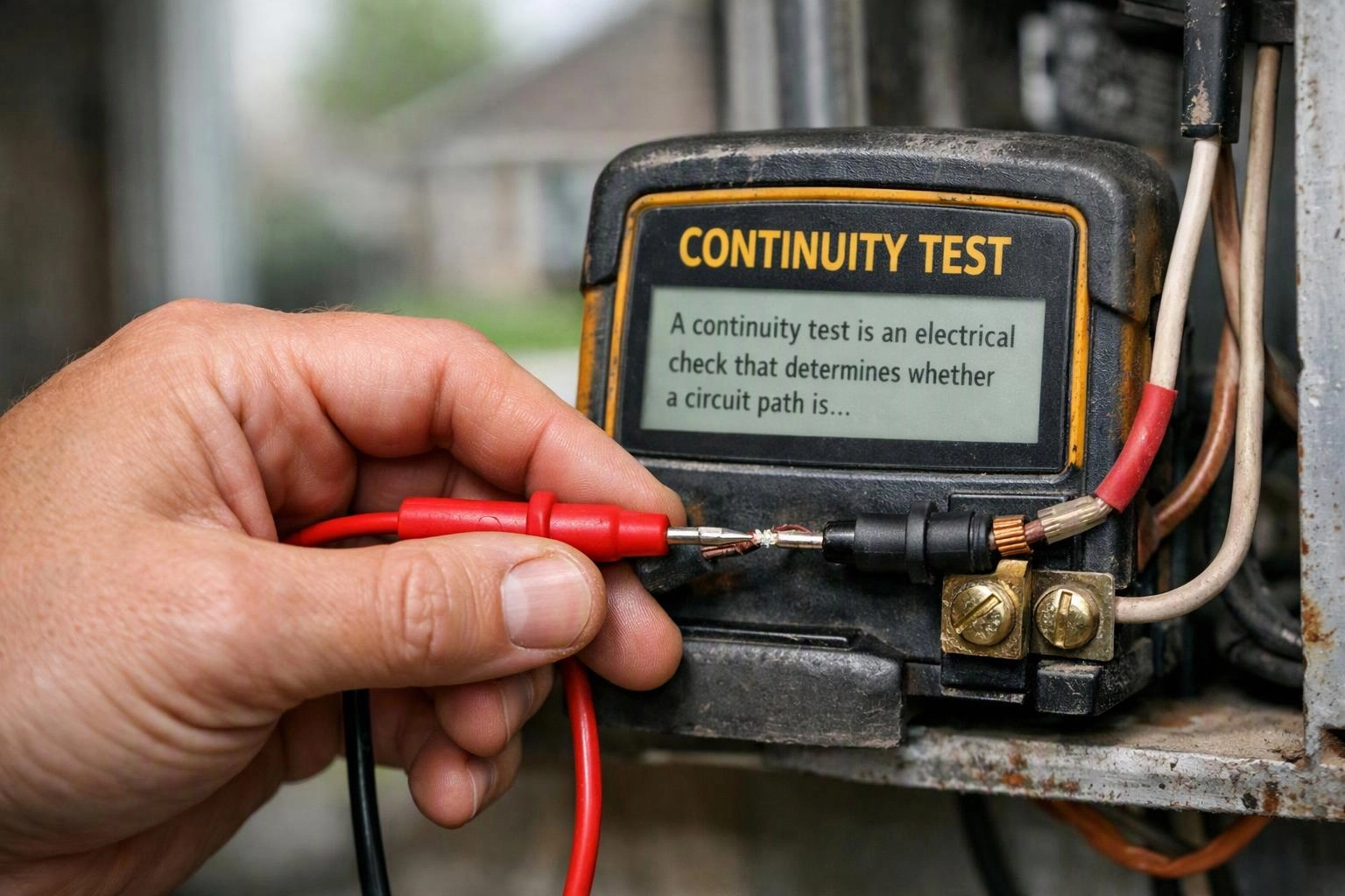
A continuity test checks the electrical path between selected points with a meter. The meter sends a small signal through the conductor or component. A complete path produces a continuity indication, while a break produces no indication or a different reading.
Related glossary terms: Multimeter, Wiring Diagram, Open Neutral.
Technicians compare the test points with the circuit layout to locate the fault. An open wire, loose terminal, failed switch, or damaged fuse can interrupt the path. The test applies to individual conductors and components, while a multimeter provides the test reading. A wiring diagram helps identify the correct points for comparison.
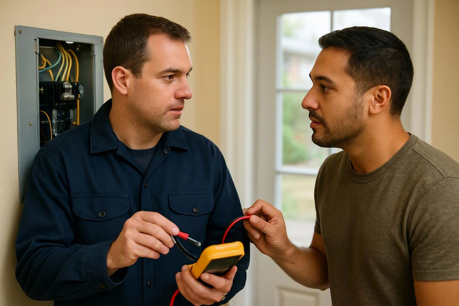
From the GMB Electric team
When we troubleshoot a circuit, we use continuity testing to trace a suspected open path between accessible points. Our team compares the meter result with the wiring layout and checks terminals, splices, switches, and conductors so the test supports a broader diagnosis.
Continuity Test in Practice: A Real-World Example
A wall switch does not control a light, so a technician checks continuity through the switch and related conductors. The result can show whether the switch opens and closes the circuit as intended or whether a connection interrupts the path.
Related Services
Related Terms
Multimeter
A multimeter is a handheld electrical testing instrument that measures values such as voltage, current, and…
Wiring Diagram
Wiring Diagram is a visual plan that shows how electrical devices, conductors, terminals, and protective components…
Open Neutral
An open neutral is a break or failed connection in the neutral conductor of an electrical…
GMB Electric
Have Questions About Continuity Test?
Contact GMB Electric for practical guidance on Continuity Test and related 24 hour electrician work in Indianapolis.